
A wireless charging dock for mobile robots is not just a charging pad. It is a complete mechanical, electrical, and workflow design that determines whether the robot can charge reliably every day.
For AGVs, AMRs, service robots, warehouse robots, cleaning robots, inspection robots, and other autonomous mobile systems, the charging dock must solve several problems at the same time: transmitter placement, receiver mounting, air gap, alignment tolerance, charging power, thermal design, protection, and robot parking accuracy.
A good wireless charging dock allows the robot to charge automatically without manual plug-in cables or exposed charging contacts. A poor dock design can cause slow charging, failed charging, overheating, misalignment, or unnecessary downtime.
This guide explains how to design a practical wireless charging dock for mobile robots and what information to prepare before requesting a wireless charging solution from ONEPOINTECH.
What Is a Wireless Charging Dock for Mobile Robots?
A wireless charging dock is a fixed charging position where a mobile robot receives power without a physical plug or exposed charging contact. The dock usually includes a transmitter module and transmitter coil. The robot carries a receiver coil and receiver power module.
When the robot stops at the charging position, the transmitter and receiver align within a designed tolerance. Power transfers across an air gap and is converted into controlled DC output for the robot battery or battery management system.
A typical wireless charging dock includes the below parts.
| Part | Function |
|---|---|
| Transmitter power unit | Supplies and controls power from the station side |
| Transmitter coil | Sends energy across the air gap |
| Docking structure | Holds the transmitter and guides robot positioning |
| Receiver coil | Receives energy on the robot side |
| Receiver power module | Converts received energy into DC charging output |
| Battery/BMS connection | Controls safe charging of the robot battery |
| Protection system | Helps prevent overcurrent, overvoltage, overheating, and fault operation |
| Optional communication | Allows charging status, start/stop control, or system diagnostics |
For a broader overview of contactless power in industrial applications, see ONEPOINTECH’s guide to industrial wireless charging.
Why Dock Design Matters for Reliable Wireless Charging
Wireless charging performance depends on more than the charger’s wattage. Even a good wireless charging module can perform poorly if the dock is not designed correctly.
Dock design affects:
- Whether the robot can park accurately
- Whether the transmitter and receiver coils align properly
- How much air gap exists between the coils
- How much charging power can be transferred safely
- How much heat is generated
- Whether the receiver fits inside the robot
- Whether the transmitter is protected from impact
- Whether the dock works in the real operating environment
- Whether charging can start automatically
- Whether the system is easy to maintain
For mobile robots, the charging dock is part of the robot’s operating system. It should be designed around the robot’s battery, body structure, route, stopping accuracy, and charging strategy.
Main Types of Wireless Charging Docks
There are several common dock designs for mobile robots. The best option depends on robot shape, ground clearance, mounting space, charging power, and workflow.
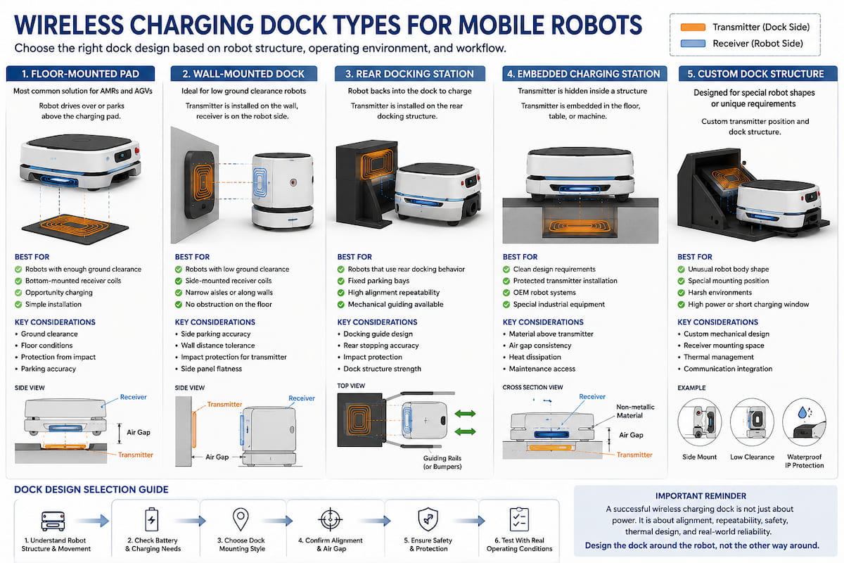
1. Floor-Mounted Charging Pad
A floor-mounted wireless charging dock places the transmitter coil on or inside the floor. The robot carries the receiver coil underneath its body.
This design is common for AMRs, AGVs, and warehouse robots because the robot can drive over or park above the charging pad.
Best for:
- Robots with enough ground clearance
- Bottom-mounted receiver coils
- Parking-zone charging
- Opportunity charging stations
- Warehouse and factory routes
Important design questions:
- What is the robot’s ground clearance?
- Can the receiver be mounted underneath the robot?
- Will the transmitter be surface-mounted or flush-mounted?
- Can the pad survive floor traffic, impact, dust, or water?
- How accurately can the robot stop over the pad?
A floor-mounted dock can be simple and effective, but the air gap and alignment tolerance must be carefully checked.
2. Wall-Mounted Charging Dock
A wall-mounted dock places the transmitter coil on a wall, frame, or vertical docking station. The receiver is mounted on the side of the robot.
This design is useful when the robot has limited ground clearance or when the facility does not want a charging pad on the floor.
Best for:
- Robots with low ground clearance
- Side-mounted receiver designs
- Narrow parking areas
- Charging along walls or docking lanes
- Robots with flat side panels
Important design questions:
- Can the robot stop close enough to the wall?
- Is the side panel suitable for receiver installation?
- Will the robot body create too much distance between coils?
- Is a mechanical guide needed?
- Can the transmitter be protected from impact?
A wall-mounted dock can work well when the robot has repeatable side positioning.
3. Rear Docking Station
A rear docking station allows the robot to back into a charger. The transmitter may be installed on the rear dock structure, and the receiver is installed at the back of the robot.
Best for:
- Robots that already use rear docking behavior
- Applications with fixed parking bays
- Robots that need controlled final alignment
- Charging stations with mechanical guides
- Environments where floor pads are not preferred
This approach can improve repeatability because the dock can physically guide the robot into the correct position.
4. Embedded Charging Station
An embedded charging station hides the transmitter inside a floor, machine, table, kiosk, production fixture, or custom dock.
Best for:
- Clean design requirements
- Protected transmitter installation
- OEM robot systems
- Specialized industrial automation equipment
- Custom mobile robot applications
Embedded designs require careful planning because the material between the transmitter and receiver affects wireless charging performance. Plastic, wood, glass, or non-metallic materials may be possible depending on thickness and design, but metal between the coils can interfere with power transfer and heating behavior.
5. Custom Dock Structure
Some projects need a custom dock instead of a standard floor or wall pad. This may happen when the robot has an unusual body shape, unusual battery voltage, limited receiver space, special communication requirements, or strict environmental requirements.
Custom dock design may include:
- Custom transmitter housing
- Custom coil shape
- Side-mounted charging
- Low-clearance charging
- Waterproof or dust-resistant enclosure
- Mechanical guide rails
- Docking bumpers
- Integrated communication
- Special cable routing
- High-power charging system
ONEPOINTECH can help evaluate whether a standard wireless charging module or a custom design is more suitable for your robot.
Transmitter Placement Options
The transmitter is the station-side charging component. It must be placed where the robot can reach it consistently.
Common transmitter placements include:
| Transmitter Placement | Best For | Notes |
|---|---|---|
| On-floor pad | AMRs and AGVs with bottom receiver | Simple to understand; must handle floor traffic |
| Flush floor installation | Clean traffic areas | Requires more installation planning |
| Wall-mounted transmitter | Side receiver designs | Useful for low-clearance robots |
| Rear docking structure | Fixed parking bays | Can improve alignment |
| Loading/unloading station | Opportunity charging | Works when robot naturally waits there |
| Parking area | Idle-time charging | Good for scheduled charging |
| Custom fixture | OEM integration | Best for specialized robots |
The transmitter should be placed where the robot naturally stops. If the robot must travel far away from its workflow to charge, the charging dock may reduce efficiency.
Receiver Coil Mounting Options
The receiver coil is installed on the robot side. Its position affects alignment, air gap, heat, cable routing, and mechanical protection.
Common receiver mounting options include:
| Receiver Position | Best For | Design Notes |
|---|---|---|
| Bottom-mounted receiver | Floor charging pads | Check ground clearance and protection |
| Side-mounted receiver | Wall docks | Check body panel thickness and alignment |
| Rear-mounted receiver | Back-in docking | Good for fixed parking stations |
| Front-mounted receiver | Front docking | May need impact protection |
| Internal embedded receiver | OEM robot design | Best when designed early |
| Custom receiver housing | Harsh environments | Useful for dust, water, vibration, or impact |
The receiver should be mounted as close to the transmitter as practical while staying protected from collision, water, dust, and mechanical damage.
For lower-power robot projects, ONEPOINTECH’s 200W wireless charging module may be suitable when the robot has longer idle time, smaller battery capacity, or light-duty operation.
For medium-duty mobile robots, AGVs, and AMRs, ONEPOINTECH’s 800W wireless charging module may be more suitable when the dock needs faster charging during shorter stops.
For high-power charging requirements, ONEPOINTECH’s 3000W wireless charger may be relevant for larger industrial vehicles or short charging windows.
Air Gap and Alignment Tolerance
Air gap and alignment tolerance are two of the most important design factors in a wireless charging dock.
The air gap is the distance between the transmitter coil and receiver coil. Alignment tolerance describes how much position error the system can accept while still charging safely and effectively.
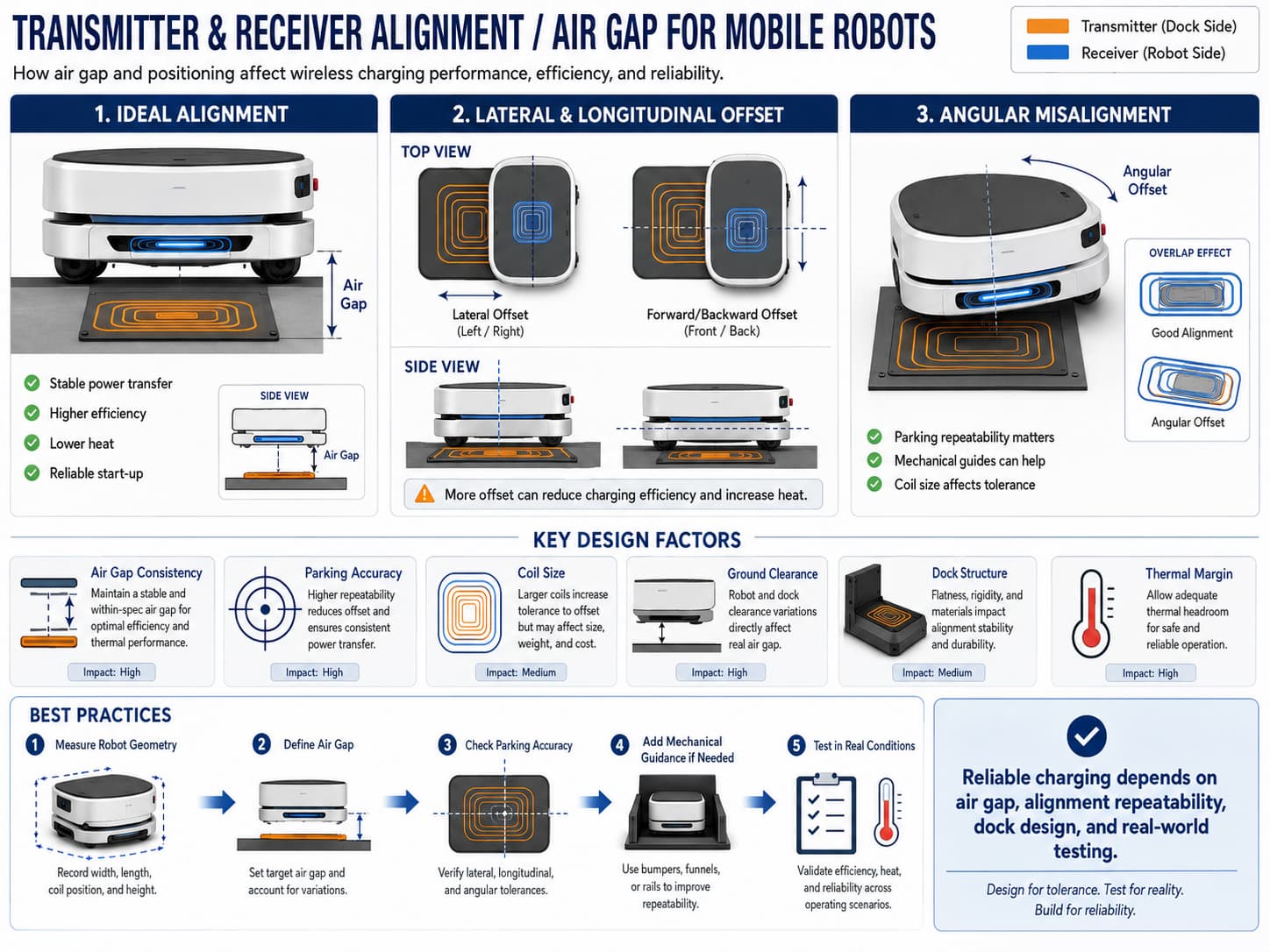
Wireless charging performance can be affected by:
- Vertical air gap
- Left-right offset
- Forward-backward offset
- Angular offset
- Coil size
- Coil shape
- Transmitter and receiver housing thickness
- Material between the coils
- Robot parking accuracy
- Charging power
- Thermal design
A smaller and more consistent air gap is usually easier to design around. A larger air gap may require a different coil design, lower power, larger transmitter/receiver area, or more thermal margin.
Docking Accuracy and Mechanical Guide Design
Mobile robots do not always stop in exactly the same position. Floor condition, wheel slip, load weight, navigation accuracy, and traffic can all affect final parking accuracy.
If the robot cannot park accurately enough, the wireless charging dock may need mechanical guidance.
Mechanical guide options include:
- Side rails
- Wheel guides
- Docking funnel
- Bumper alignment
- Rear stop plate
- Visual marker
- Magnetic positioning reference
- Floor marking
- Parking tolerance zone
- Software-based final alignment routine
The goal is to make the final charging position repeatable. The better the repeatability, the easier it is to design a stable wireless charging system.
Dock Design for Low Ground Clearance Robots
Low ground clearance can make floor-mounted wireless charging difficult because there may not be enough space for the receiver, housing, and safe air gap.
For low-clearance robots, consider:
- Side-mounted receiver
- Wall-mounted transmitter
- Rear docking station
- Thin receiver housing
- Custom coil design
- Recessed floor transmitter
- Protected embedded pad
- Smaller air gap design
- Mechanical alignment guide
A low-profile design may require a custom transmitter/receiver layout. In this case, send ONEPOINTECH the robot body dimensions, ground clearance, receiver mounting area, and dock layout before choosing a module.
Charging Power Selection for the Dock
Charging power should be selected based on battery voltage, battery capacity, charging time, opportunity charging strategy, and BMS limits.
As a general direction:
| Charging Need | Possible Direction |
|---|---|
| Small robot, long idle time, light-duty charging | 200W range |
| Medium-duty AGV/AMR, shorter charging stops | 800W range |
| Larger vehicle, high energy demand, short charging window | 3000W or custom system |
| Unusual voltage, coil, dock, or enclosure requirements | Custom design |
The dock must also handle the heat and physical size of the selected charging system. Higher power usually requires more attention to thermal design, cable routing, station protection, and installation space.
ONEPOINTECH’s LC180-A30 may also be relevant for projects where its form factor and electrical characteristics match the robot’s charging requirements.
Safety and Protection Features
A robot wireless charging dock should be designed with safety and protection in mind.
Important protection considerations include:
- Overvoltage protection
- Overcurrent protection
- Short-circuit protection
- Over-temperature protection
- Receiver detection
- Misalignment handling
- Foreign object protection
- Safe start/stop behavior
- Emergency stop integration
- Mechanical protection from impact
- Cable protection
- Waterproof or dust-resistant housing if needed
For industrial projects, safety should be designed at the system level. The charger, battery, BMS, robot controller, enclosure, dock structure, and operating environment should all be considered together.
Communication and Control
Some wireless charging docks only provide power. Others may need communication between the charger, robot controller, battery management system, or fleet management software.
Communication can help with:
- Charging start/stop control
- Battery voltage monitoring
- Charging current monitoring
- Charging status
- Fault reporting
- Temperature warning
- Robot presence detection
- Dock availability
- Fleet scheduling
Depending on the project, communication may use CAN, RS485, UART, GPIO, or a custom control interface.
Material Between the Transmitter and Receiver
The material between the transmitter and receiver can affect wireless charging performance.
In general:
| Material Type | Design Consideration |
|---|---|
| Plastic | Often suitable depending on thickness and temperature |
| Wood | May be suitable for some embedded applications |
| Glass | May be suitable depending on thickness and mechanical design |
| Rubber | May be suitable but should be checked for heat and thickness |
| Metal | Usually problematic between coils and should be avoided |
| Composite materials | Must be tested case by case |
Do not assume that a wireless charger will perform the same after it is installed behind a thick panel or inside a metal structure. The real mechanical design should be tested.
Where to Install the Dock in the Workflow
A wireless charging dock should be placed where the robot naturally stops. Good locations include:
- Loading points
- Unloading points
- Parking zones
- Waiting areas
- Conveyor transfer points
- Production line buffers
- Maintenance zones
- Route endpoints
- Dispatch areas
The dock should not block human walkways, forklift routes, emergency exits, or robot traffic. It should also be protected from impact, water, and debris.
If the robot uses opportunity charging, placing docks at natural waiting points is usually better than forcing the robot to leave its workflow.
Common Mistakes in Wireless Charging Dock Design
Mistake 1: Choosing the Charger Before Checking the Robot Geometry
The charger should fit the robot, not the other way around. Check receiver space, ground clearance, body panel thickness, and cable routing before selecting a module.
Mistake 2: Ignoring Real Parking Accuracy
A robot may park accurately in a demo but less accurately in a real warehouse or factory. Test real docking behavior before finalizing coil size and dock structure.
Mistake 3: Making the Air Gap Too Large
A large air gap can reduce efficiency, increase heat, and make high-power charging harder. Keep the gap as small and consistent as practical.
Mistake 4: Placing Metal Between Coils
Metal between the transmitter and receiver can interfere with wireless charging and create heating problems. Avoid metal in the charging path unless the system is specifically designed for that structure.
Mistake 5: Forgetting Thermal Design
Higher power creates more heat. Receiver placement, enclosure design, airflow, and charging duration should be checked before deployment.
Mistake 6: Treating the Dock as Only a Mechanical Part
A wireless charging dock is a system. It includes power electronics, coils, battery interface, protection, mechanical structure, software behavior, and workflow planning.
Wireless Charging Dock Design Flow
A practical dock design should follow a structured process.
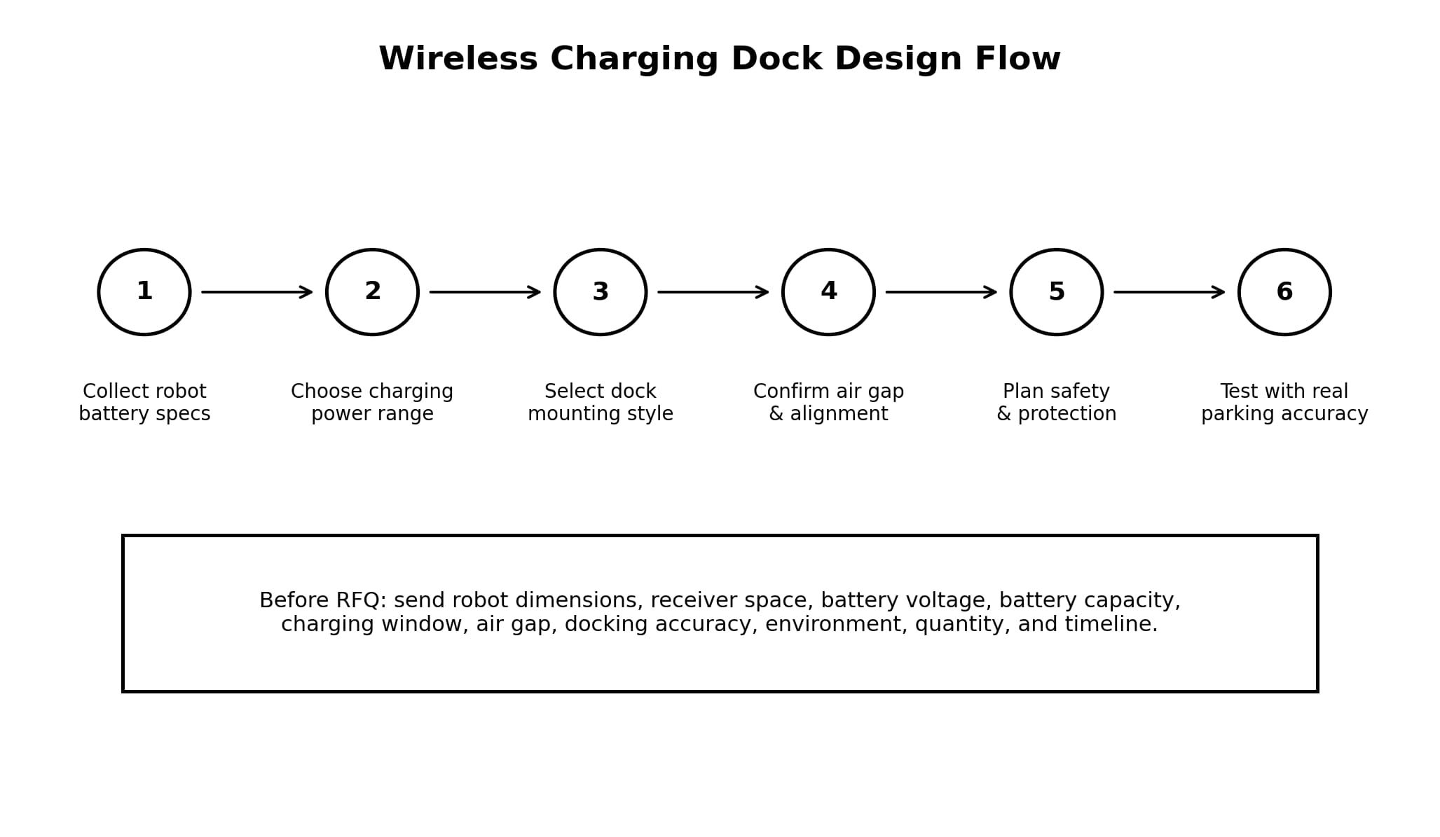
Step 1: Collect Robot Battery Specs
Start with battery voltage, capacity, chemistry, maximum charging current, and BMS requirements.
Step 2: Choose the Charging Power Range
Select a planning range such as 200W, 800W, 3000W, or custom based on the robot’s charging window and energy demand.
Step 3: Select Dock Mounting Style
Choose floor-mounted, wall-mounted, rear-docking, embedded, or custom mounting based on robot shape and workflow.
Step 4: Confirm Air Gap and Alignment
Measure the real distance between transmitter and receiver and estimate parking tolerance.
Step 5: Plan Safety and Protection
Include overcurrent, overvoltage, temperature, foreign object, misalignment, and emergency behavior as needed.
Step 6: Test with Real Parking Accuracy
Test the dock with real robot movement, load conditions, floor conditions, and charging cycle timing.
Wireless Charging Dock Specification Checklist
Before asking ONEPOINTECH for a recommendation, prepare the following information:
| Requirement | What to Prepare |
|---|---|
| Robot type | AGV, AMR, service robot, cleaning robot, inspection robot, custom mobile robot |
| Robot dimensions | Length, width, height, ground clearance |
| Receiver mounting area | Bottom, side, rear, front, or custom |
| Battery voltage | 24V, 36V, 48V, or custom |
| Battery capacity | Ah or Wh rating |
| Battery chemistry | Lithium, LiFePO4, lead-acid, or other |
| Maximum charging current | BMS or battery limit |
| Desired charging time | Full charge time or opportunity charging window |
| Dock style | Floor, wall, rear, embedded, or custom |
| Air gap | Distance between transmitter and receiver |
| Alignment tolerance | Expected parking accuracy |
| Environment | Indoor, outdoor, wet, dusty, cold, hot, cleanroom |
| Communication | CAN, RS485, UART, GPIO, or none |
| Protection needs | FOD, temperature, overcurrent, overvoltage, emergency stop |
| Target product | 200W, 800W, LC180-A30, 3000W, or custom |
| Quantity | Sample, pilot, or production |
| Timeline | Prototype and mass production schedule |
FAQ: Wireless Charging Dock Design for Mobile Robots
What is the best wireless charging dock design for a mobile robot?
The best dock design depends on robot shape, ground clearance, battery size, charging power, air gap, parking accuracy, and operating environment. Floor-mounted docks are common, but wall-mounted, rear-docking, and custom embedded designs may be better for certain robots.
Should the transmitter be installed on the floor or wall?
Use floor mounting when the receiver can be installed underneath the robot and the ground clearance is suitable. Use wall or side mounting when the robot has low ground clearance or a better side receiver location.
Where should the receiver coil be placed?
The receiver should be placed where it can align consistently with the transmitter while staying protected from impact, dust, water, and heat. Common positions include bottom, side, rear, and custom embedded locations.
How much air gap is acceptable?
The acceptable air gap depends on coil design, charging power, alignment tolerance, and system efficiency. In general, a smaller and more consistent air gap is easier to design for.
Can wireless charging work for low ground clearance robots?
Yes, but the dock may need side-mounted charging, rear docking, recessed transmitter installation, a thin receiver design, or a custom coil layout.
What charging power should I choose for a robot dock?
Small robots may use a 200W range. Medium-duty AGVs and AMRs may use an 800W range. Larger industrial vehicles or short charging windows may require 3000W or custom power.
Does the robot need to stop perfectly over the charging pad?
No system should rely on perfect parking. The dock should be designed around the robot’s real stopping accuracy and alignment tolerance.
Can a wireless charging dock support opportunity charging?
Yes. Wireless charging docks are especially useful for opportunity charging because the robot can charge automatically during short stops without manual connection.
What materials can be between the transmitter and receiver?
Non-metallic materials such as plastic, wood, glass, or rubber may be possible depending on thickness and thermal behavior. Metal between the coils should generally be avoided.
What should I send to ONEPOINTECH for dock design support?
Send robot dimensions, battery voltage, battery capacity, maximum charging current, receiver mounting space, desired charging power, air gap, alignment tolerance, dock style, operating environment, quantity, and timeline.
Conclusion
Wireless charging dock design is a key part of reliable mobile robot charging. The dock must match the robot’s mechanical structure, battery system, route, stopping accuracy, charging power, and environment.
A good dock design can support automatic charging, reduce manual plug-in work, avoid exposed charging contacts, and make opportunity charging easier. A poor dock design can cause misalignment, heat, slow charging, and failed charging attempts.
For small robots, a 200W wireless charging module may be enough. For medium-duty AGVs and AMRs, an 800W wireless charging module may provide a better balance of charging speed and integration complexity. For larger industrial vehicles or short charging windows, a 3000W wireless charger or custom wireless charging system may be needed.
Need help designing a wireless charging dock for a mobile robot?
Send ONEPOINTECH your robot dimensions, battery voltage, battery capacity, maximum charging current, receiver mounting space, air gap, alignment tolerance, dock style, operating environment, and estimated quantity. Our engineering team can help recommend a suitable 200W, 800W, LC180-A30, 3000W, or custom wireless charging solution for your project.