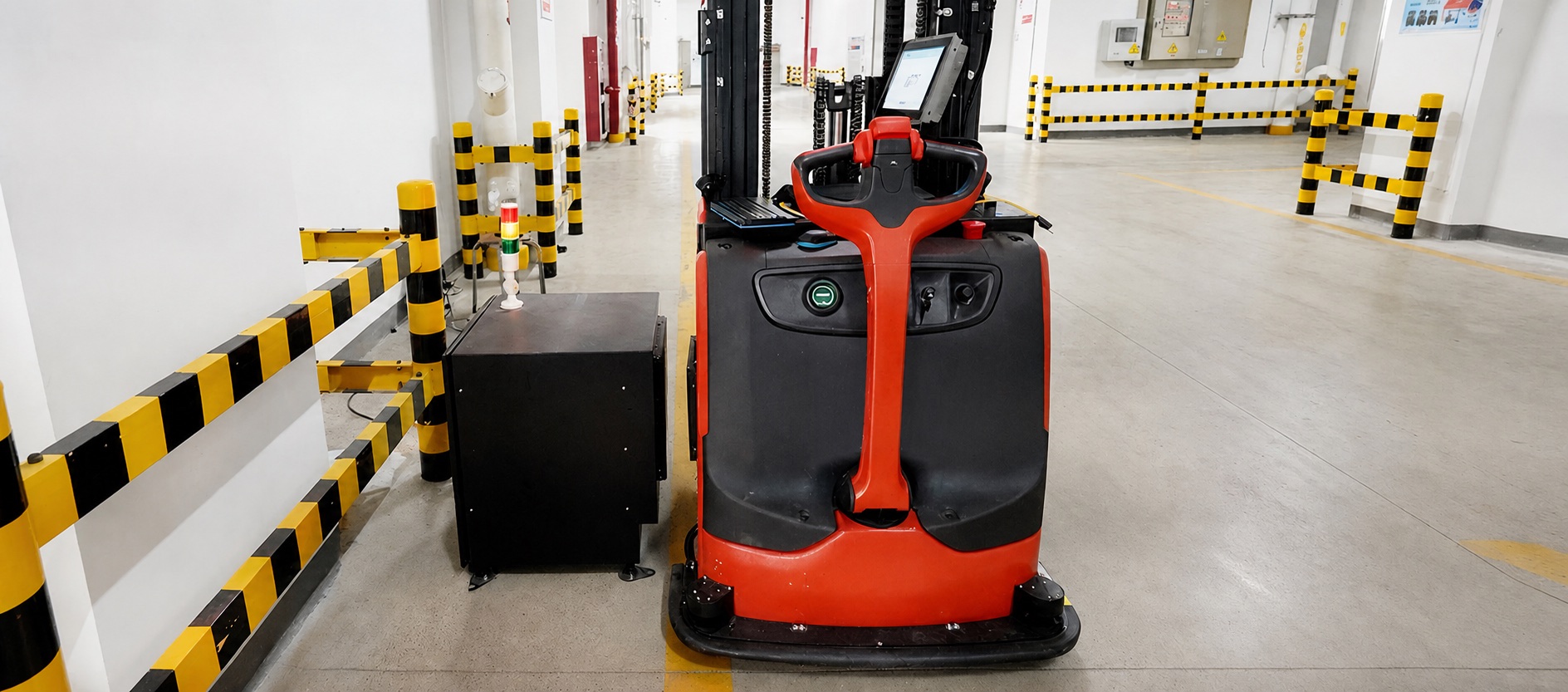
Industrial vehicle aligned beside a wireless charging station

Industrial wireless charging for AGVs, AMRs & forklifts

Compare contactless 1.5kW, 3kW and 6kW charging systems for AGVs, AMRs, forklifts and mobile robots — then check the electrical, mechanical and communication fit for your fleet.

Three systems, one architecture

Choose by power class, then verify the fit.

Start with battery voltage, charge current and the time available at each stop. Each system uses the same contactless architecture with different electrical and mechanical envelopes.

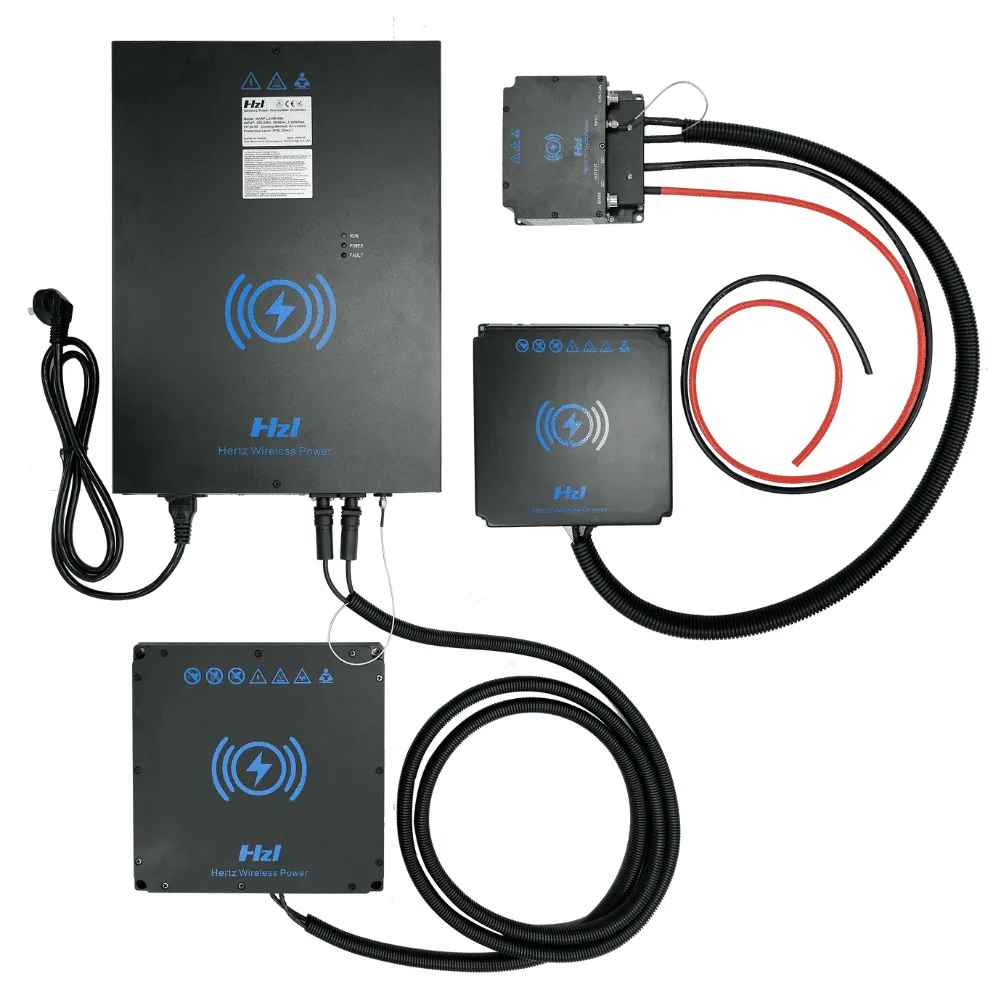
LC180-A30 — 1.5kW System

SYSTEM · DC 18-60V/30A

LC180-A30 — 1.5kW System

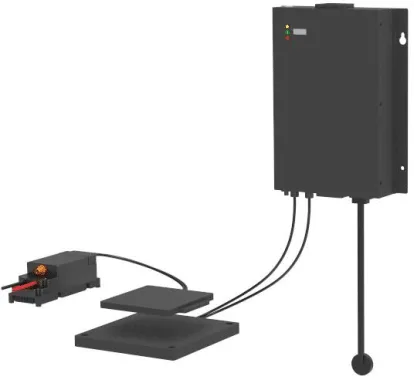
A plug-and-play 1.5kW wireless charging system with a wide output range, compatible with 24V, 36V and 48V battery systems. Universal AC input makes deployment simple anywhere in the world.

Best for · AGVs, AMRs & service robots

LS300-A60 — 3kW System

SYSTEM · DC 42-58V/60A

LS300-A60 — 3kW System

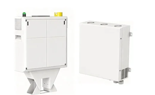
A complete AC-input wireless charging system for heavy industrial vehicles. Mount the transmitter pad, connect to mains power, and your fleet charges automatically at every stop — no plugs, no contacts, no wear.

Best for · Unmanned forklifts & heavy AGVs

LC600-A100 — 6kW System

SYSTEM · DC 15-60V/100A

LC600-A100 — 6kW System

The LC600-A100 pushes contactless charging to 6kW with up to 100A of charging current. Built for heavy AGVs, forklifts and high-throughput automation where every minute of charging time counts.

Best for · Heavy AGVs & high-throughput fleets

System comparison

Three power classes. Different electrical and mechanical envelopes.

Values below come from the current product data. “Max” and “optimal” conditions matter; use the linked datasheets and confirm the final configuration before purchase.

Comparison of ONEPOINTECH 1.5kW, 3kW and 6kW industrial wireless charging systems
SpecificationLC180-A30LS300-A60LC600-A100
Continuous charging power1.5kW max3kW max6kW max
Charging voltage18–60V42–58V15–60V
Charging current30A max60A max100A max
Charging distance10–30mm; 20mm optimal20–45mm; 40mm optimal20–60mm optimum range
Position tolerance±20mm X/Y±40mm one axis; ±25mm both axes±30mm
InterfaceCAN / RS485CAN / RS485CAN / RS485
Protection classCoils IP65; RX IP54; TX IP20Coils IP65; RX IP54; TX IP20IP20
Listed certificationsUL, CSA, FCC, CE, RoHS, REACHUL, CSA, FCC, CE, REACHNone listed

Swipe horizontally to compare all systems.

Mechanism

How AGV & AMR wireless charging works.

  • Transmitter pad — in the floor or at the side

    A flat pad mounts flush in the floor or against a side wall at a repeatable stop, sealed against dust and water.

  • Receiver on the vehicle — underside or side

    A coil mounts on the vehicle's underside or side face and wires into the onboard charger and BMS.

  • Air gap + alignment

    Power transfers across the air gap when the vehicle parks within the published gap and tolerance window.

Does the route contain enough charging time?

Wireless charging removes manual connection, but the energy balance still has to work. Estimate the energy consumed per route and the time available at repeatable stops before selecting system power.

Battery limits

Voltage, chemistry, capacity and permitted charge current.

Duty cycle

Energy per route, stop duration, frequency and operating hours.

Charging geometry

Coil gap, mounting face, approach and parking variation.

Site conditions

Input power, temperature, exposure, access and compliance market.

Estimate required power
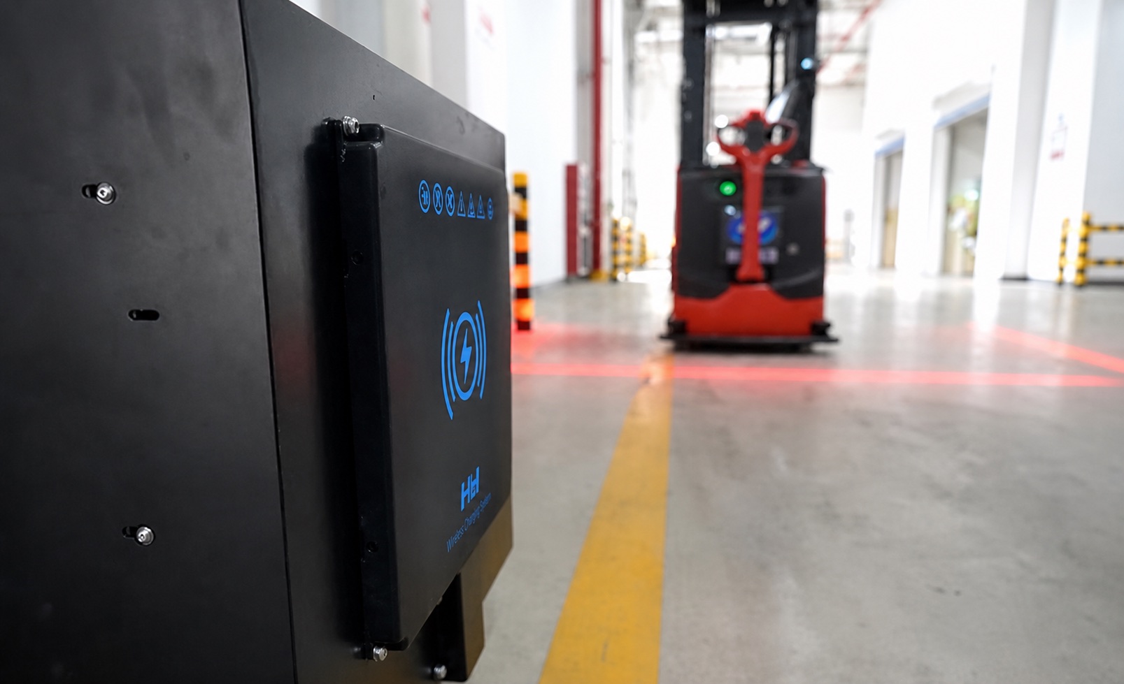
Wireless charging pad in an industrial facility with a vehicle in the background

Opportunity charging workflow

Turn existing stops into controlled charging events.

  1. 1

    Approach

    The fleet controller routes the vehicle to a defined charging position.

  2. 2

    Confirm

    Vehicle position, battery state and charger readiness are checked.

  3. 3

    Charge

    The system transfers power within the validated gap and alignment window.

  4. 4

    Release

    Charging stops according to the agreed BMS and fleet-control logic.

Application fit

Where an automated charging interface may help.

Match the application to a power class, then confirm the Fits system against voltage, current and charging geometry.

1.5–3kW

AGVs and AMRs

Place charging at repeatable stops such as queues, work cells or parking positions.

Fits · LC180-A30 · LS300-A60

3–6kW

Unmanned forklifts

Evaluate higher-power charging against route pauses, battery current limits and mounting space.

Fits · LS300-A60 · LC600-A100

1.5kW

Mobile robots

Coordinate rear, side or floor-facing receiver geometry with docking and navigation.

Fits · LC180-A30

1.5–6kW

Automated equipment

Use sealed contactless interfaces where exposed charging contacts are undesirable.

Fits · LC180-A30 · LS300-A60 · LC600-A100

Industrial wireless charging pad in a facility

Certifications

Certification status differs by system.

Certificates are issued per model and market. The LC180-A30 and LS300-A60 list UL, CSA, FCC and CE marks; no certifications are listed for the LC600-A100 in the current product data. Confirm the exact configuration and destination-market requirements before ordering.

Certified

LC180-A30

1.5kW

  • UL 1564
  • CSA C22.2
  • FCC Part 15
  • CE (EMC)
  • RoHS
  • REACH
Certified

LS300-A60

3kW

  • UL 1564
  • CSA C22.2
  • FCC Part 15/18
  • CE (EMC)
  • REACH
None listed

LC600-A100

6kW

No certifications are listed in the current product data. Confirm the exact configuration and destination-market requirements before ordering.

FAQ

Questions engineers ask before evaluation.

Straight answers on system fit, opportunity charging, alignment, communications and certification status.

Which system should I evaluate first?

Start with battery voltage, maximum permitted charging current and the time available at each charging stop. The 1.5kW system covers a broad 18–60V output range, the 3kW system is intended for 42–58V lithium platforms, and the 6kW system covers 15–60V at up to 100A. Mechanical gap, alignment, environment and communications must also be reviewed before selection.

Can wireless charging support opportunity charging?

Yes. A transmitter can be placed at locations where a vehicle already pauses, allowing short charging sessions during the normal route. Whether those sessions provide enough energy depends on route timing, battery capacity, state-of-charge limits and system power. Use the calculator for an initial estimate, then validate the duty cycle with your engineering team.

How accurately must the vehicle park?

The published position tolerance depends on the model and test condition: LC180-A30 lists ±20mm in X/Y, LS300-A60 lists ±40mm on one axis or ±25mm on both axes, and LC600-A100 lists ±30mm. The final mounting design should be tested on the actual vehicle and navigation system.

How does the charger communicate with the vehicle or battery?

The system range lists CAN and RS485 interfaces. The specific message set, control responsibilities and BMS behavior should be agreed during integration. Charging should not be enabled until electrical, thermal, mechanical and communication checks have passed.

Are all three systems certified in the same way?

No. Certification status differs by model. The LC180-A30 datasheet lists UL 1564, CSA C22.2, FCC Part 15, CE EMC, RoHS and REACH. The LS300-A60 datasheet lists UL 1564, CSA C22.2, FCC Part 15/18, CE EMC and REACH. No certifications are listed for the LC600-A100 in the current product data. Confirm the exact configuration and destination-market requirements before ordering.

Can I test one charging point before a fleet rollout?

Use the inquiry form to request an evaluation discussion. A sensible validation plan covers charging time, alignment, temperatures, fault handling, communication, mounting and the real route before production quantities are considered.

Request an engineering review

Bring the battery and route. We’ll help narrow the system.

Useful inputs include battery voltage and chemistry, permitted charge current, energy used per cycle, stop duration, coil gap, mounting direction, environment and expected quantity.

Please include relevant specifications, installation constraints and expected quantity.

Volume pricing available. Request a quote for quantity-based pricing.