
ISO 21423:2026 is a communications and interoperability standard for industrial mobile robots, fleet managers and other equipment in shared industrial environments. For an autonomous mobile robot (AMR) charging project, the practical question is how fleet coordination connects to the robot’s battery and charging controls.
A shared fleet communication approach does not, by itself, make wireless chargers interchangeable. A working charging installation still needs compatible power hardware, an agreed control sequence and validation with the actual battery. ONEPOINTECH’s engineering perspective is to define those interfaces together before selecting a charging system.
What changed with ISO 21423:2026?
The Association for Advancing Automation (A3) announced the standard on November 2, 2026. Its announcement describes communication requirements that help industrial mobile robots, fleet managers and other equipment exchange information and request actions across vendors.
ISO’s publication record records publication on October 14, 2026. Its public abstract explicitly excludes safety and navigation requirements. It also excludes entertainment, consumer, military, medical and public-road applications; the industrial scope should not be generalized to every mobile robot.
This analysis is based on the public ISO abstract and A3 announcement; the full standard has not been reviewed. The charging examples below are ONEPOINTECH’s proposed integration checks.
Where fleet coordination meets charging control
A fleet manager may decide which robot should charge and when a station is available. The vehicle controller, battery management system (BMS) and charger then need their own agreed conditions for starting, regulating and stopping power transfer. These responsibilities interact, but answer different questions.
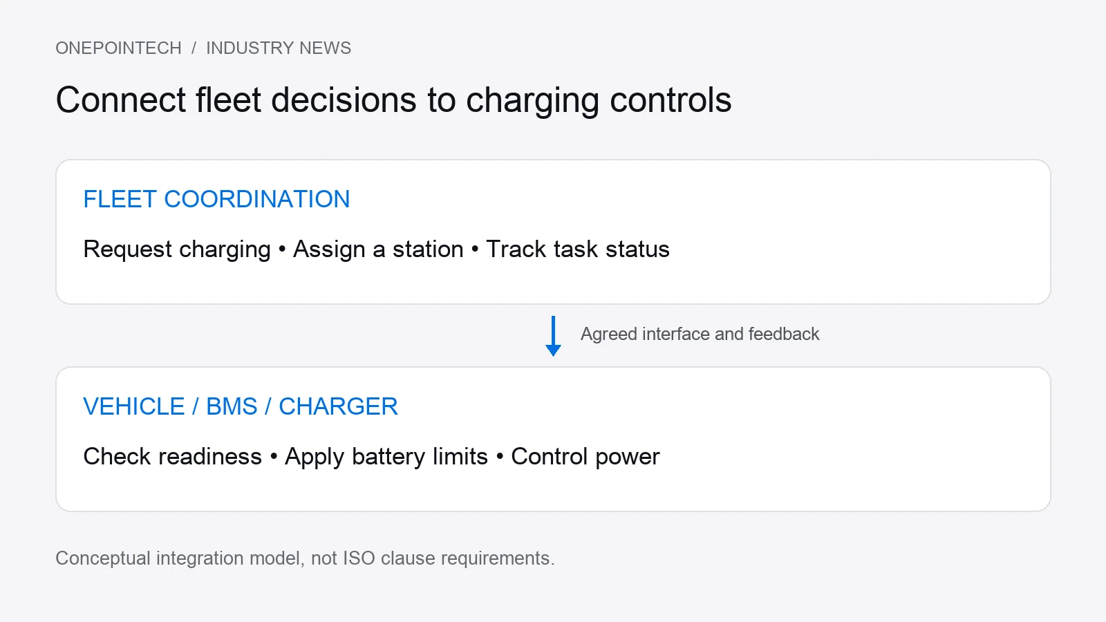
For example, a fleet manager could assign a charging task while the battery is outside its permitted charging temperature. The local controls must apply the battery’s limits, and the integration needs a defined response: report charging unavailable, retain or release the station reservation, and decide what the robot should do next.
A CAN or RS485 connection alone does not establish that both ends interpret the same messages. Teams must agree on the applicable protocol, message definitions, units, update timing and timeout behavior. Our industrial charger communication guide explains the charger-side interface considerations.
Five charging integration checks before commissioning
Agree on responsibilities and expected outcomes when the robot supplier, fleet software team and charging supplier prepare an interface specification. The following project checklist helps structure that discussion.
| Decision | What the team should define | What to test |
|---|---|---|
| Request and reservation | Who requests charging, assigns a station and releases it. | Two robots request the same station. Confirm how conflicting reservations, cancellations and delays are resolved. |
| Ready to charge | How positioning, charger readiness and battery charge permission are confirmed. | Alignment or battery permission is invalid. Confirm charging is inhibited and the unavailable state is reported. |
| Power regulation | Who provides voltage and current limits, and how changed limits reach the charger. | The BMS reduces allowable current. Confirm the charger follows the revised limit within the agreed response time. |
| Fault and interruption | How faults, stale data and communication loss affect charging and task status. | Interrupt a communication link. Confirm the specified response to missing data and the recovery sequence. |
| Completion and departure | What ends the session, confirms power transfer has stopped and authorizes departure. | Reach the charge target or cancel the task. Confirm power transfer stops before departure is authorized. |
Document safety responsibilities in the interface specification and coordinate them with the installation’s safety assessment. Communication interoperability does not replace protection design, battery validation or the applicable product and machinery requirements.
How to specify the wireless charging hardware
Fleet-level coordination cannot resolve a mismatch in battery voltage, charging current or coil installation. Before choosing hardware, document the battery chemistry and charge limits, route energy consumption, available charging time, receiver space, coil gap and expected positioning variation.
For automated guided vehicle (AGV) and AMR projects, ONEPOINTECH’s range includes the LC180-A30 charging system and LS300-A60 charging system. Review each product’s specifications and datasheet against the project requirements. These product references do not constitute a claim of ISO 21423 compliance or compatibility with a particular fleet manager.
Use the AMR charging station specification guide to prepare the hardware requirements, alongside the interface questions above. The AGV and AMR wireless charging overview provides the wider system-selection context.
Discuss your charging integration requirements
Send ONEPOINTECH your battery datasheet, required charging window, mounting drawing and proposed control interface. Include the intended responsibilities of the fleet manager, vehicle controller and BMS, plus any available message documentation. These inputs help identify the hardware and integration questions that need resolving before a charging trial.