
SYSTEM · DC 18-60V/30A
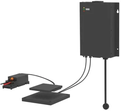
LC180-A30 — 1.5kW System
Universal-input turnkey system for 24V/36V/48V platforms
Industrial · Application
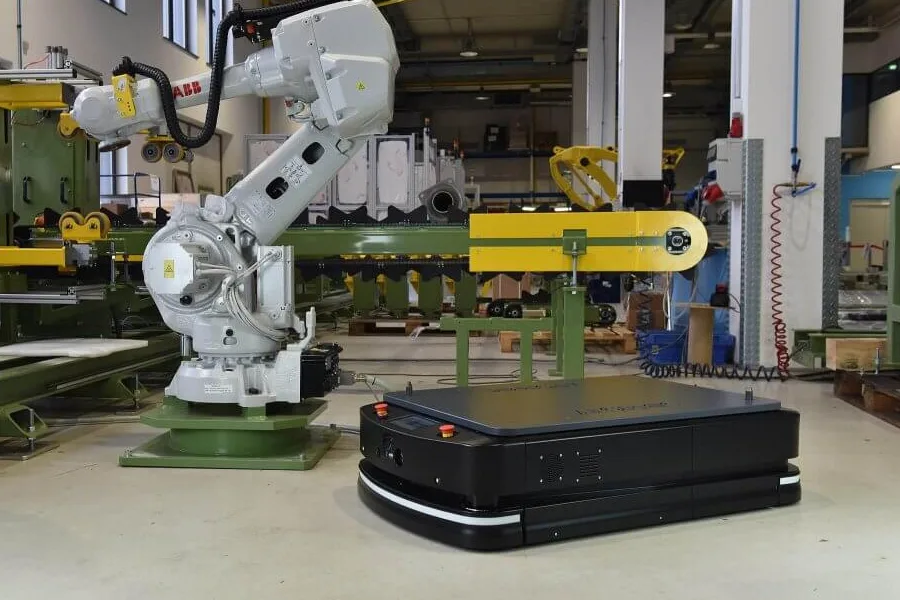
AGV wireless charging uses a stationary transmitter and a receiver installed on the vehicle to charge its battery automatically across an air gap. It enables charging at loading stations, work cells and parking positions without plugs or exposed electrical contacts.
Specifications reviewed against current product datasheets · Updated September 23, 2026
Turnkey systems
SYSTEM · DC 18-60V/30A
Universal-input turnkey system for 24V/36V/48V platforms
SYSTEM · DC 42-58V/60A
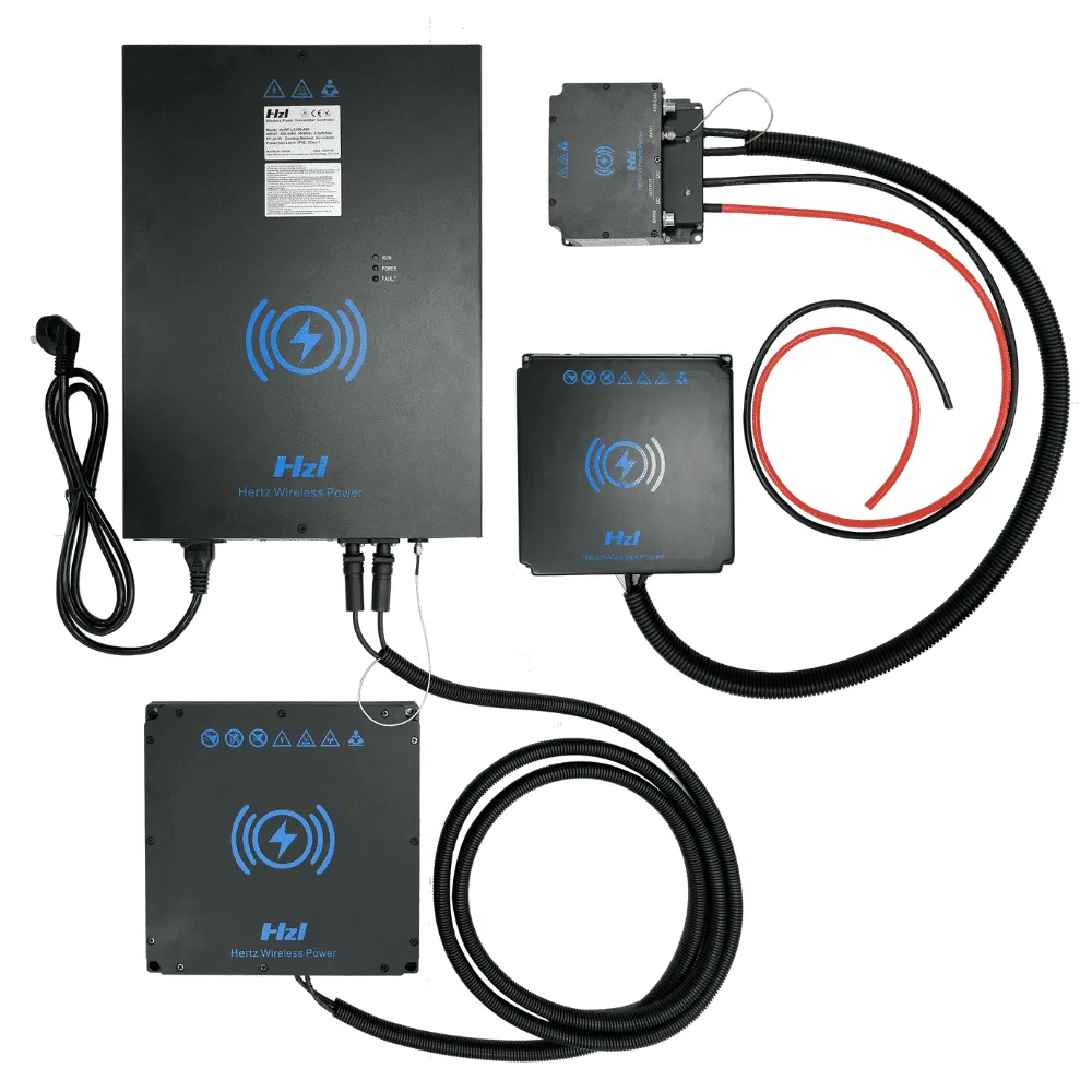
Heavy-duty contactless charging for AGVs and forklifts
SYSTEM · DC ≤60V/100A
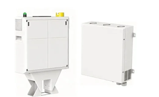
Our most powerful charger — 6kW for heavy industrial fleets
25+
Countries served
2019
Founded
1.5kW–6kW
Industrial power range
Industry deployments
Contactless power systems deployed by leading automation, robotics and logistics companies






Datasheet comparison
These are published values for each matched transmitter and receiver system. Charging gap, alignment tolerance and efficiency are model-specific; do not transfer a value from one model to another.
| Model | Output | Efficiency | Coil gap | Position tolerance | Communication | Component enclosure ratings | Source |
|---|---|---|---|---|---|---|---|
| LC180-A301.5kW max | 18–60V DC / 30A max | >80% | 10–30mm; 20mm optimal | 20mm X/Y; 10° max tilt | CAN / RS485 | Coils IP65; RX controller IP54; TX controller IP20 | PDF datasheet ↗ |
| LS300-A603kW max | 42–58V DC / 60A max | 90% max at optimum distance | 20–45mm; 35–40mm optimal | ±40mm one axis; ±25mm both axes | CAN / RS485 | Coils IP65; RX controller IP54; TX controller IP20 | PDF datasheet ↗ |
| LC600-A1006kW max | Up to 60V DC / 100A max at 220V AC input | ≥85% | 20–40mm | ±30mm | CAN / RS485 | TX unit IP20; TX coil IP67; RX unit IP20 | PDF datasheet ↗ |
All values are maxima, ranges or test-point results from the linked manufacturer datasheets. Final selection requires battery, route, mounting and environmental review.
Inside ONEPOINTECH
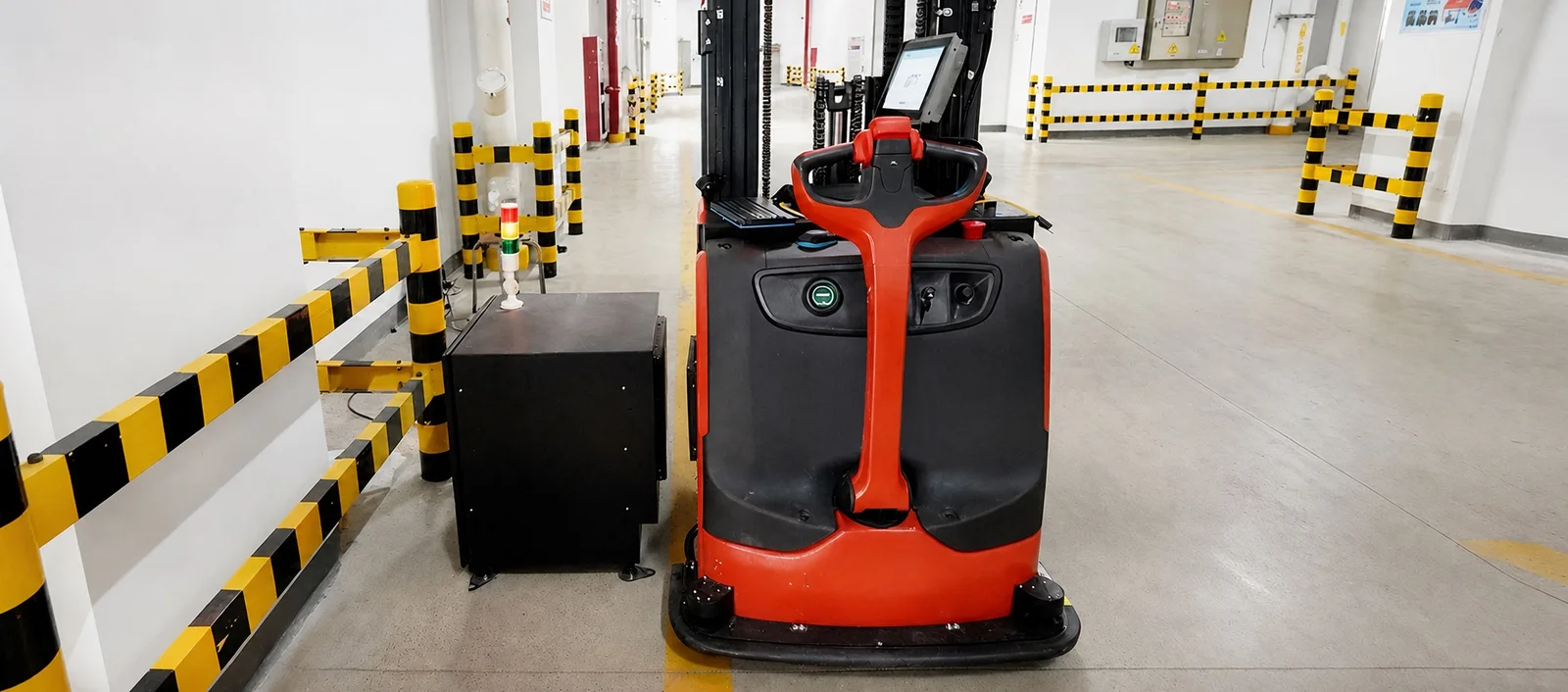
See how industrial wireless charging systems are assembled and prepared, then examine a real automatic forklift charging installation.
System architecture
An AGV wireless charging station transfers energy across an air gap without exposed electrical contacts. A matched transmitter and receiver pair, the vehicle battery and its BMS, and the fleet-control logic must be engineered as one system.

The fleet controller sends the vehicle to a repeatable floor-, side- or rear-facing charging position.
Position, battery state, communications and charger readiness are checked before power transfer starts.
The transmitter energizes its coil and the onboard receiver supplies controlled DC power to the battery.
The BMS or fleet logic ends the session and returns the AGV to its route.
Charging strategy
| Design factor | Wireless charging | Contact charging |
|---|---|---|
| Interface | Sealed transmitter and receiver coils | Exposed pins, plates or brushes |
| Maintenance | No mating contacts to clean or replace | Contact wear, contamination and alignment require inspection |
| Automation | Automatic start at validated stopping points | Automatic operation is possible but depends on reliable physical contact |
| Trade-off | Higher initial integration cost and a defined coil window | Lower initial complexity but a wearing electrical interface |
Add energy during loading, unloading or parking when the route, dwell time and battery charge-current limit support it.
Contactless power removes charging pins and brushes that otherwise require cleaning, alignment checks and eventual replacement.
Published position tolerance ranges from 20mm to ±40mm depending on the selected system and whether one or both axes are offset.
CAN or RS485 interfaces support charger coordination, provided the project defines messages, interlocks and failure behavior.
Engineering selection
Start with energy consumed per route and the time available at natural stops. Then confirm battery limits, charging geometry, communications and site conditions. A higher-power charger only helps when the battery can accept the current and the vehicle remains over the pad long enough.
Chemistry, nominal and maximum voltage, capacity, permitted current and BMS protocol.
Energy per route, operating hours, stop frequency and available dwell time.
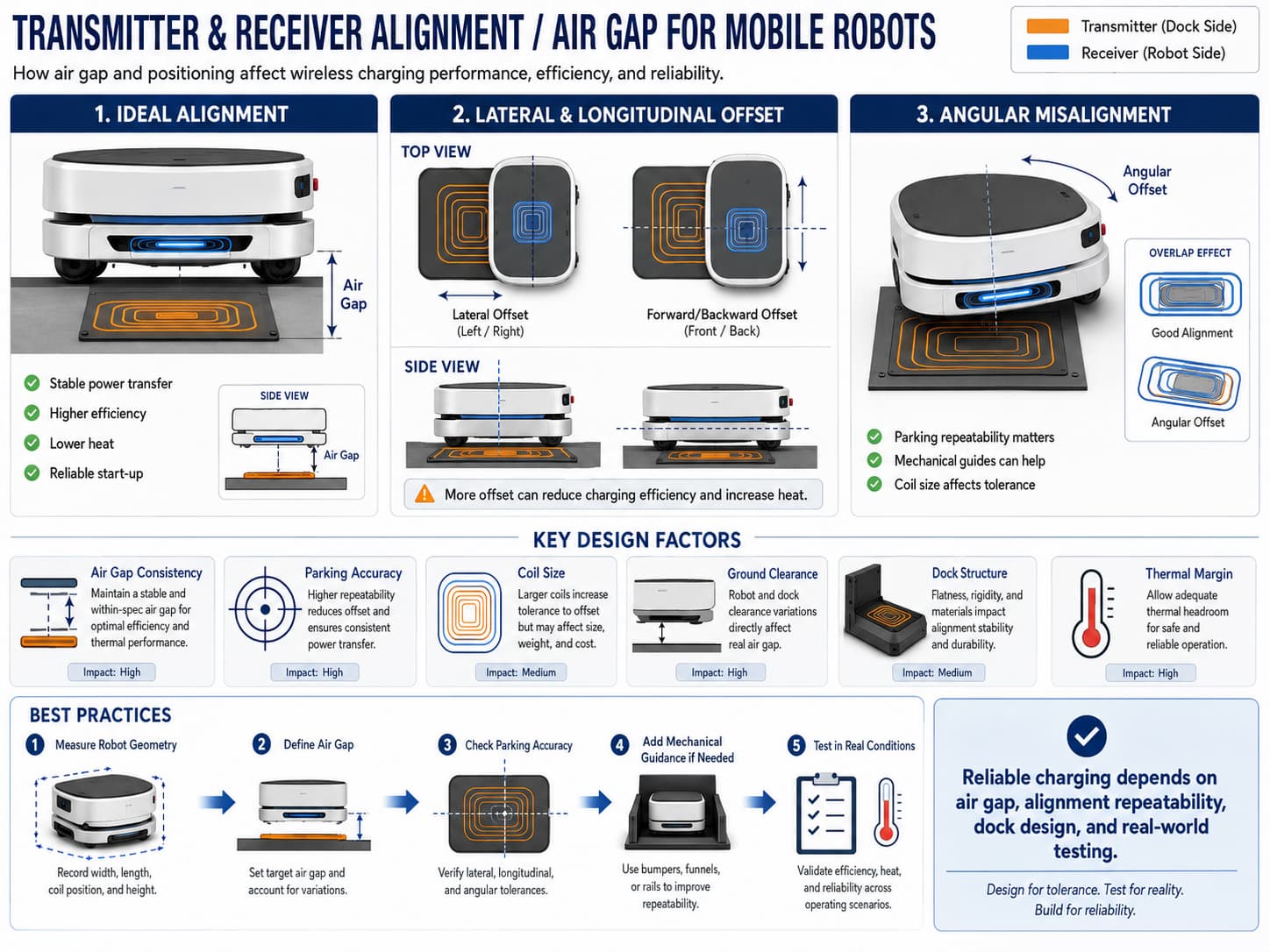
Coil gap, mounting face, parking repeatability, X/Y offset and angular variation.
Temperature, dust, water, debris, cleaning, vibration and impact exposure.
Charge enable, interlocks, CAN or RS485 messages and fleet-manager behavior.
Current, efficiency, temperature and start/stop behavior at nominal and worst-case alignment.
Applications
Wireless charging is useful wherever autonomous vehicles return to predictable points but exposed contacts create maintenance, contamination or availability problems. The charging location and power class should follow each workflow.
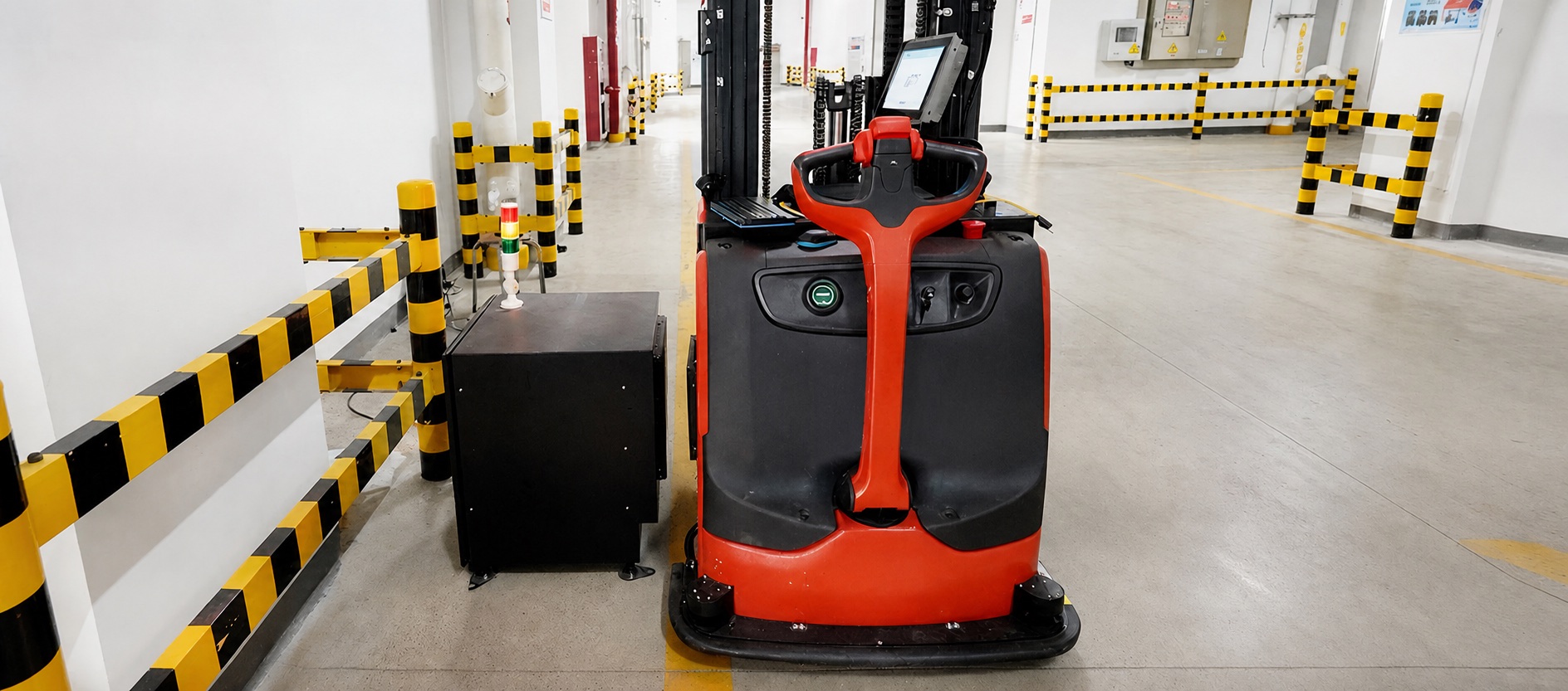
Charge pallet movers, tuggers and transport AGVs at loading bays, conveyor transfers, queues and parking positions.
Use work-cell dwell time to recharge parts-delivery AGVs without interrupting takt-driven material supply.
Power material-handling vehicles serving machining, welding, packaging and finished-goods routes across multiple shifts.
Support higher-energy lift trucks at pallet handoff points or dedicated automatic docks after checking battery-current limits.
Remove exposed charging contacts where contamination or cleaning routines reduce connector reliability. Confirm the component enclosure ratings and cleaning method for the selected system.
Place charging at repeatable staging or transfer points for baggage, cargo and internal-logistics vehicles.
Allow delivery and service AMRs to recharge at dispatch stations without staff handling plugs or charge contacts.
Standard systems described here are intended for industrial indoor use. Outdoor projects require additional environmental protection or a project-specific configuration and site validation.
Fleet planning
01
Short sessions occur during natural process stops. This can reduce dedicated charging time and battery size, but the accumulated energy delivered per shift must exceed route consumption plus operating margin.
02
Vehicles visit a defined charger based on state of charge or a schedule. It is simpler to control and meter, but requires enough stations and route capacity to prevent charging queues.
03
Frequent top-ups handle normal operation while longer scheduled sessions restore reserve or balance the fleet. Hybrid planning is useful when dwell time varies by shift or route.
Estimate battery-side energy used per route, multiply charger output by actual charging time, and apply measured system efficiency. If an AGV uses 0.5kWh per loop and stops for five minutes, the charger must restore that energy within the available stops—without exceeding the battery’s permitted current. Add margin for traffic, aging, temperature and missed charging events. Use the industrial charging power calculator for an initial estimate, then validate it with measured vehicle data.
Mechanical + electrical + controls
From specification to fleet rollout
Record energy consumption, stop locations, dwell-time distribution, daily operating hours and charging opportunities.
Document chemistry, capacity, nominal and maximum voltage, permitted charge current and BMS interface.
Select a system and mounting orientation that fit the energy balance and the available vehicle space.
Combine navigation repeatability, floor variation, payload, tires, brackets and coil placement in X, Y, Z and angle.
Test start-up, full-load charging, misalignment limits, temperature, communications and abnormal conditions.
Roll out approved hardware and track energy, missed sessions, alarms, temperature and battery state across the fleet.
Business case
Wireless equipment may cost more initially than a simple contact interface. Compare complete lifecycle costs: charging stations, vehicle receivers, installation, controls work, battery capacity, connector replacement, cleaning, maintenance labor, charging downtime and the number of vehicles needed to meet throughput. Use measured route and maintenance data instead of assuming wireless charging automatically reduces fleet size.
Commissioning evidence
Test the production-intent vehicle at minimum and maximum coil gap, X/Y offset, angular variation, light and heavy payload, and relevant temperatures. Record delivered current, DC-to-DC efficiency, component temperature, startup reliability and fault recovery. The approved window—not one ideal laboratory point—is the specification the fleet must maintain.
Common questions
A stationary transmitter coil creates a magnetic field when an AGV stops at a validated charging position. A receiver coil on the vehicle converts that field into DC power for the battery. The charger, BMS and fleet controller coordinate charging over the configured control interface.
Required power depends on energy used per route, available dwell time, battery voltage and permitted charging current. ONEPOINTECH offers complete 1.5kW, 3kW and 6kW systems; the correct size must be calculated from the vehicle duty cycle rather than vehicle size alone.
Yes. Opportunity charging places charging stations at repeatable pauses such as loading, unloading, queuing or parking. The fleet can receive small, frequent charges without a separate manual charging shift when the energy balance supports it.
Industrial wireless chargers can be configured for lithium-ion and LiFePO4 batteries within the voltage and current range of the selected system. Battery chemistry, maximum voltage, permitted charge current and BMS interface must be confirmed before selection.
Parking tolerance is model-specific. Coil gap, X/Y offset and angular alignment must all remain inside the validated operating window. Do not apply the tolerance of one model to another; verify the installation using the selected transmitter and receiver pair.
Often, yes, if the vehicle has space for the receiver coil and controller, the battery and BMS can accept the charger output, and a repeatable charging position can be created. A retrofit review should cover mounting, cable routing, ground clearance, communications, thermal behavior and safety interlocks.
There is no universal best orientation. Floor mounting keeps the station out of aisle traffic but must handle debris, drainage and ground clearance. Side and rear mounting can simplify access and cleaning but need impact protection and a repeatable docking face.
Efficiency depends on the matched system, coil gap, alignment, load and measurement boundary. ONEPOINTECH model data lists peak DC-to-DC efficiency for specific test points; project validation should measure the selected transmitter and receiver across the real operating window.
The principal cost drivers are charger power, number of stations, vehicle receivers, installation work, controls integration, certification needs and custom mechanical design. Total-cost analysis should also include connector maintenance, labor, downtime, battery capacity and fleet availability.
Engineering guides
2026-08-10
AGV Battery Charging Systems: Methods, Sizing & Wireless
Read guide →2026-06-04
AGV Charging Station Design: Wireless vs Contact-Based Docking
Read guide →2026-06-10
AMR Charging Station Specification Guide for Engineers
Read guide →2026-06-08
Opportunity Charging for AGV and AMR Fleets Explained
Read guide →2026-06-05
How to Choose Charging Power for AGV and AMR Batteries
Read guide →2026-06-09
Wireless Charging Dock Design for Mobile Robots
Read guide →2026-09-21
Wireless Charging Distance and Offset Tolerance: An Industrial Design Guide
Read guide →2026-09-19
Industrial Wireless Charger Certifications: UL 1564, CSA, FCC, CE and TÜV Explained
Read guide →Engineering RFQ
Share your battery, vehicle, route and charging-window requirements. Our engineers will recommend a suitable 1.5kW, 3kW or 6kW system and identify the integration questions to resolve before a pilot.
Email info@onepointech.com
Phone +86 156 1877 5325