
Wireless charging distance is not a single number to maximise. It is a mechanical operating window that has to survive the real variation in a robot, AGV or forklift: parking error, floor unevenness, tyre wear, suspension movement, payload, mounting tolerances and protective covers.
A design can look acceptable on a drawing and still fail in operation if its nominal coil gap sits at the edge of the charger's range. The same is true of alignment. A datasheet may list an offset tolerance, but the vehicle can consume that allowance through several independent errors before it reaches the dock.
This guide explains how to specify wireless charging distance, X/Y offset and angular alignment as an engineering tolerance stack. The model values below come from the current ONEPOINTECH datasheets; they are not universal limits for wireless power transfer.
What wireless charging distance actually measures
For an industrial inductive charging system, the charging distance is the gap between the active coupling surfaces of the transmitter coil and the receiver coil. It is commonly labelled the Z-axis distance.
It is not automatically the same as:
- Ground clearance. A floor-mounted transmitter, covers, brackets and the receiver's mounting position all sit inside the vehicle-to-floor dimension.
- Enclosure-to-enclosure distance. The controller housings may be mounted away from the coils.
- Dock clearance. A side-mounted dock can include guards or locating features that do not define the magnetic gap.
- Maximum detection distance. Communication or presence detection does not prove that the system can transfer rated power at that position.
Define the measurement faces on the mechanical drawing. If the transmitter has a protective cover or the receiver sits behind a non-metallic panel, show whether that thickness is included in the coil-to-coil distance. Ambiguous datum points are a common source of installation error.
Rated range, optimum distance and design distance are different
Three distances matter during selection:
- Rated charging range — the interval in which the matched system is specified to operate.
- Optimum distance — the point or narrower band at which the supplier reports the best coupling or efficiency.
- Design distance — the nominal value on your machine drawing after allowing for real mechanical variation.
The design distance should normally sit near the optimum value, with enough room on both sides for the full tolerance stack. It should not be chosen simply because it is the maximum number in the datasheet.
| System | Maximum power | Rated coil distance | Published alignment data | Useful reference point |
|---|---|---|---|---|
| TE03 module | 200W | 15–35 mm | Measured test data includes 10 mm and 20 mm offsets | 91% at 25 mm in the datasheet |
| TF02 module | 800W | 25–35 mm | ±15 mm misalignment | 93% at 30 mm |
| LC180-A30 | 1.5kW | 10–30 mm | 20 mm X/Y position tolerance; 10° maximum tilt | 20 mm optimum |
| LS300-A60 | 3kW | 20–45 mm | ±40 mm in X or Y alone; 25 mm when X and Y are both offset; 10° relative inclination | 35–40 mm optimum |
| LC600-A100 | 6kW | 20–40 mm | ±30 mm position tolerance | Confirm the project test point |
These values are model-specific. Do not mix the distance from one system with the offset tolerance or efficiency from another. Transmitter and receiver coils are a matched pair, and power level alone does not determine their operating window.
Offset tolerance is a two-dimensional requirement
Offset describes how far the centre of the receiver coil can move away from the centre of the transmitter coil in the plane of the coils. On a floor-mounted system, this is normally split into:
- X-axis offset — left-right error across the travel path.
- Y-axis offset — front-back stopping error along the travel path.
- Combined X/Y offset — diagonal error when both occur at the same time.
The distinction matters. The LS300-A60 datasheet permits a 40 mm offset when displacement occurs in one direction, but lists 25 mm when X and Y are both offset. That does not describe the same operating point as ±40 mm in both axes simultaneously. A procurement specification that says only "40 mm tolerance" loses the condition that makes the figure meaningful.
Angular error is separate again. A vehicle can stop over the correct centre point while the coil faces are no longer parallel. Both the LC180-A30 and LS300-A60 list a 10° angular limit. For a side-mounted charger, chassis roll or dock deflection may create the angle; for a floor-mounted charger, tyre pressure, suspension and floor slope can contribute.
Why distance and offset affect charging performance
The transmitter and receiver transfer energy through a coupled magnetic field. Increasing the gap, moving the coil centres apart or tilting one face changes that coupling. The practical symptoms can include lower charging current, reduced efficiency, additional heat or a failure to start charging if the system falls outside its permitted window.
That relationship is not a licence to invent one universal derating curve. Coil geometry, operating frequency, control electronics, load and test method all matter. Use measurements for the exact transmitter-receiver pair at the intended power.
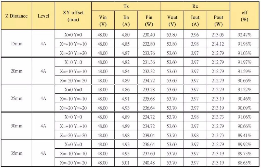
ONEPOINTECH's existing TE03 200W test article provides a useful example. Under the documented test conditions, system efficiency was about 92% at a 15–20 mm gap, remained above 91% at 25–30 mm and was about 90% at 35 mm. Separate tests covered 10 mm and 20 mm coil offsets across gaps from 15 mm to 35 mm. At a charging distance within 30 mm and an offset within 20 mm, the measured system achieved approximately 90% efficiency.
Build an installation tolerance stack
The correct nominal position comes from adding the errors that can occur in service, not from copying the charger's maximum tolerance into the docking requirement.
For the Z-axis gap, evaluate:
- transmitter and receiver bracket tolerances;
- protective-cover thickness and manufacturing variation;
- floor flatness or dock-frame movement;
- tyre wear, tyre pressure and wheel diameter;
- suspension travel and payload-dependent ride height;
- thermal or structural deflection;
- debris that can prevent the vehicle reaching its normal position.
For X/Y position and angle, evaluate:
- the navigation system's stopping repeatability, not only its stated localisation accuracy;
- approach direction and speed;
- floor traction and wheel slip;
- dock guides, wheel stops or mechanical locating features;
- coil placement tolerance on every vehicle in the fleet;
- chassis yaw, pitch and roll at the charging point.
A simple design check is:
available operating margin = charger limit − worst-case installation and docking variation
Run that check independently for minimum gap, maximum gap, X offset, Y offset and angle. If the remaining margin is close to zero, changing the nominal distance will not solve every axis; the project may need a more repeatable dock, a different coil position or a system with a larger approved window.
Example: selecting a nominal gap
Consider an LC180-A30 installation with a rated 10–30 mm coil distance and a stated optimum of 20 mm. Suppose the mechanical review finds that the actual gap can vary by 4 mm above or below nominal after combining mounting, floor and vehicle variation.
- A 20 mm nominal design produces an expected range of 16–24 mm.
- A 28 mm nominal design produces an expected range of 24–32 mm.
The second design crosses the 30 mm rated maximum even though the drawing's nominal value appears to be inside the published range. The first stays within the range and around the optimum point. This is why a rated maximum should be treated as a boundary, not a target.
The calculation is deliberately simple. A safety-critical or high-volume project should use the organisation's normal tolerance-analysis method and validate the result with production-representative hardware.
Docking accuracy should be measured on the real vehicle
A navigation specification does not fully describe coil alignment. The final coil position includes localisation error, control response, braking, wheel slip, mechanical mounting and the relationship between the robot's reference point and the receiver centre.
Measure repeated arrivals at the intended charging location with:
- the lightest and heaviest normal payloads;
- new and worn tyres where relevant;
- representative approach directions and speeds;
- the actual floor or dock structure;
- the protective covers and brackets fitted;
- normal contamination and temperature conditions.
Record the final X, Y and Z positions and coil angle, then compare the distribution with the system's limits. Averages are not enough: the failed charge at the edge of the distribution is what interrupts an autonomous workflow.
For a new integration, a one-vehicle pilot is the quickest way to establish the real window. Test the centre position first, then the expected extremes, while recording delivered current, efficiency, temperature and start/stop behaviour. The robot wireless charging dock design guide covers the wider mechanical and control architecture around that test.
Mounting material and nearby metal still matter
A correct gap does not compensate for an unsuitable installation. Conductive metal close to the active coupling area can heat and can change system behaviour. Follow the model's clearance drawings, use the specified magnetic shielding and do not bury a coil in a metal cavity unless the installation is explicitly designed and tested for it.
Protective layers in the power-transfer path should be non-metallic and included in the measured coil gap. Cable routing also has specified clearances on the full systems; do not treat the high-frequency coil cable as an ordinary power lead or change its length without approval.
For bottom-mounted coils, the design also has to manage debris and foreign objects. For side-mounted coils, check impact protection and ensure the dock cannot force the two faces closer than the permitted minimum. The alignment solution must protect the equipment as well as place it accurately.
What to put in an RFQ or design specification
Use measurable requirements rather than asking for "long-distance" or "large-tolerance" charging. Include:
| Input | What to specify |
|---|---|
| Battery | Chemistry, nominal and maximum voltage, capacity, permitted charging current and BMS interface |
| Power requirement | Required battery-side power, target dwell time and energy required per stop |
| Nominal coil gap | Defined coupling-surface datums and the proposed Z-axis distance |
| Gap variation | Minimum and maximum after covers, payload, tyres, floor and mounting tolerances |
| Position variation | Measured X and Y parking error, including combined diagonal cases |
| Angular variation | Maximum pitch, roll or yaw between coupling faces |
| Mounting | Floor, side, front or rear location; drawings; materials; nearby metal and available space |
| Environment | Temperature, water, dust, debris, cleaning method, vibration and impact exposure |
| Validation | Required test points for gap, offset, angle, current, efficiency and temperature |
This information lets a supplier evaluate the application against a complete operating envelope rather than quoting the most favourable number from a datasheet.
Choose the system around the real operating window
The best wireless charger is not the model with the largest maximum gap. It is the matched system whose power, voltage, gap, offset, angle, thermal performance and communication fit the vehicle at the same time.
Start with a nominal installation near the supplier's optimum point. Subtract the full mechanical and docking variation from the published limits. Then validate the remaining margin on a production-representative vehicle before scaling across the fleet.
For a recommendation, send ONEPOINTECH your battery specification, required charging power, dwell time, mounting drawings, nominal gap, measured X/Y parking variation, expected angle, environment and certification market. We can evaluate the application against the 1.5kW LC180-A30, 3kW LS300-A60, 6kW LC600-A100 or an OEM module and define the test points before you commit to the dock design.
Send your gap and alignment requirements for an engineering review →