
Commercial cordless robotic pool cleaners now use wireless charging docks. The reason is practical: a pool robot operates around water, chemicals and debris, while a conventional charging connector depends on clean, dry and correctly mated electrical contacts. A wireless dock removes the exposed power connection and gives the product designer more freedom to create a sealed charging interface.
That does not mean any wireless charging module can be installed in any pool robot. The charger still has to match the battery, available charging time, coil spacing, enclosure construction and thermal conditions. For a compact cleaner built around a compatible 21V charging path, the ONEPOINTECH TD01 60W wireless charging module is a candidate for engineering evaluation. Its listed output is 21V DC / 3A, 60W.
Why pool-cleaner charging is becoming contactless
Robotic pool cleaners work in a difficult charging environment. Water can remain in seams after the robot is removed from the pool. Chlorinated or salt water can leave residue. Fine debris can settle around a port, and a user may try to connect a charger before the area is completely dry. Exposed contacts and removable covers therefore add cleaning steps, wear points and opportunities for incorrect handling.
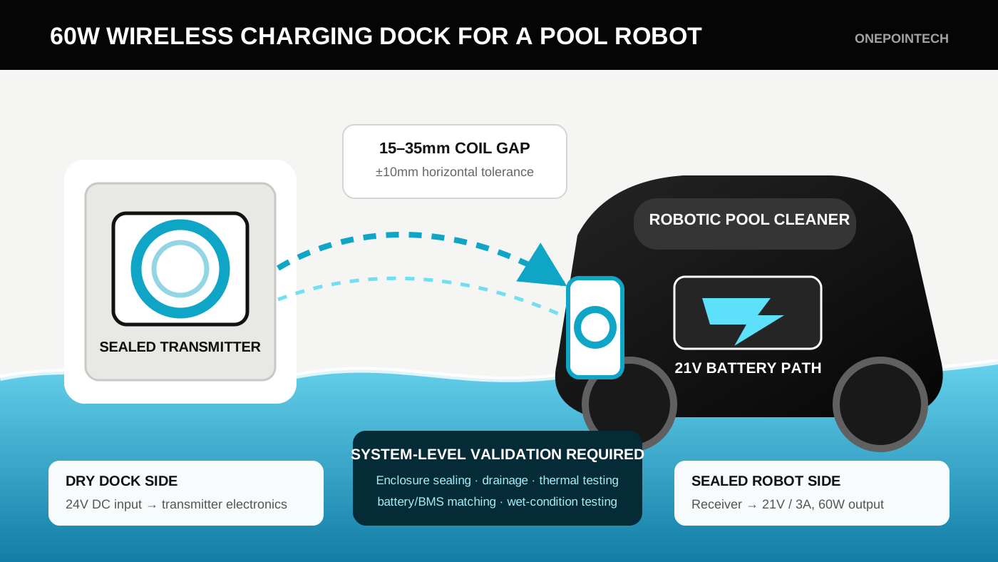
A wireless charging interface replaces the metal-to-metal power connection with two magnetically coupled coils. The dock contains the transmitter; the cleaner contains the receiver. When the coils are within the designed gap and alignment range, power crosses the sealed non-metallic walls without a plug entering the robot housing.
This is already a commercial product direction. The MOVA Rover X10 and SMOROBOT Valor P20, for example, are marketed with wireless charging docks. These products are market references only; they are not presented as ONEPOINTECH customers or TD01 integrations.
What wireless charging can improve
- No exposed charging contacts: the power interface can sit behind a sealed, electrically non-conductive wall.
- Simpler user workflow: the user places the cleaner in a cradle instead of opening a cover and inserting a connector.
- Less connector wear: there are no pins to bend, oxidize or loosen through repeated mating.
- More design freedom: the receiver can be integrated into a flat wall or docking feature rather than a user-accessible port.
- A path toward automated docking: future cleaners can potentially return to a suitable dock without a person making the electrical connection.
Wireless power does not remove the need for waterproof engineering. It changes the interface that must be sealed. The complete product still needs validated housing joints, cable entries, pressure behavior, thermal paths and safe fault handling.
Is 60W enough for a robotic pool cleaner?
There is no universal pool-robot charging wattage. The correct value depends on how much battery energy must be restored and how long the cleaner can remain on the dock. Start with battery energy rather than choosing a charger from the application name.
Battery energy (Wh) = nominal battery voltage (V) × capacity (Ah)
Ideal charging time (h) = energy to restore (Wh) ÷ charging power (W)
| Battery energy to restore | Ideal time at 60W | Engineering interpretation |
|---|---|---|
| 90Wh | 1.5 hours | Potential fit for a compact cleaner with a generous dock period |
| 120Wh | 2 hours | Potential fit if the battery accepts the available current |
| 180Wh | 3 hours | Reasonable overnight or between-cycle target |
| 240Wh | 4 hours | May work, but the product team should confirm whether the user expects faster turnaround |
| 300Wh | 5 hours | Consider a longer dock window or evaluate a higher-power architecture |
These are ideal energy calculations, not promised charge times. Actual charging takes longer because current may be limited by the BMS, the battery tapers toward full charge, the robot may consume standby power and the installed system has conversion losses. Temperature can also cause the charge controller or battery to reduce current.
Battery voltage is the first compatibility gate
TD01 provides a listed 21V DC / 3A output. That voltage must be compatible with the battery pack's full-charge voltage and the product's charge-control architecture. Nominal battery voltage is not enough. An OEM should provide the battery datasheet, including chemistry, series-cell count, maximum charge voltage, permitted charge current and BMS behavior.
Do not connect a module to a battery merely because the wattage appears suitable. A robot requiring 25.2V, 29.4V or another charge voltage is not a direct 21V match. ONEPOINTECH should review the electrical specification before a sample is selected.
How a wireless pool-robot dock works
- The dock receives DC power. For TD01, the listed transmitter input is 24V DC / 4A. The external AC adapter and mains-side construction are separate system components.
- The transmitter drives its coil. The coil creates an alternating magnetic field across the designed gap.
- The receiver captures the transferred energy. A matched coil inside the cleaner converts the field back into electrical power.
- The receiving electronics provide DC output. TD01 provides 21V / 3A, approximately 60W, for a compatible downstream charging path.
- The battery-control system manages charging. The OEM must define how the module, charger stage and BMS start, regulate and stop the charge.
The dock should locate the robot mechanically before charging begins. Ramps, side guides, tapered ribs or a shaped cradle can reduce position error without asking the user to align two invisible coils by eye. For a deeper discussion of these relationships, see the wireless charging dock design guide.
Mechanical and waterproof design
The best coil location is usually a flat, repeatable docking surface with the shortest stable path between the transmitter and receiver. The material between the coils must be non-metallic and compatible with the electromagnetic design. Metal fasteners, ballast, motors and reinforcing structures near the coil can alter coupling and create heat, so they should be reviewed during the layout stage.
Control the complete coil-to-coil gap
TD01 is specified for a 15–35mm coil-to-coil charging distance with ±10mm horizontal alignment tolerance. The gap includes more than an empty air space. It must account for:
- the transmitter enclosure wall;
- the receiver enclosure wall;
- adhesive, potting or mounting layers;
- the physical space between dock and robot;
- manufacturing tolerance and plastic deformation;
- debris or water trapped at the docking surface.
A concept that measures 25mm in CAD may exceed 35mm after housings, ribs, sealant and production tolerance are included. Build a tolerance stack before tooling the enclosure, then verify it on physical samples. The related guide to charging distance and offset tolerance explains why gap and lateral error must be tested together.
Choose a dry-dock architecture unless underwater charging is specifically engineered
The lower-risk starting point is a dock used after the cleaner is removed from the pool. It can tolerate a wet robot, but the electronic assemblies remain inside sealed housings and the station is installed according to the target market's electrical rules.
Underwater or pool-edge automatic charging is a different engineering project. It introduces immersion pressure, long-term seal exposure, biofouling, cable routing near water and installation requirements that cannot be addressed by a module datasheet alone. Do not describe TD01 as submersible or IP-rated unless the finished enclosure has been designed and tested to the required standard.
Electrical, thermal and safety integration
A charging dock must behave as a system, not a collection of parts. TD01 includes foreign-object detection and over-current, over-voltage and over-temperature protection at module level. The finished product still needs its own protection strategy covering the adapter, wiring, connectors inside sealed compartments, battery pack, BMS and user-accessible surfaces.
Define the charge-control boundary
The engineering team should document which component performs each function:
- validates that the robot is correctly docked;
- authorizes power transfer;
- limits battery voltage and current;
- reads battery temperature and state of charge;
- terminates charging;
- reports a completed or failed charging session;
- prevents immediate charging when the battery temperature is outside its permitted range.
TD01 supports UART / RS485 communication, but the required messages and control behavior must be agreed during integration. Communication availability should not be treated as automatic compatibility with an existing robot protocol.
Plan for heat inside a sealed housing
Sealing electronics against water also makes it harder for heat to escape. TD01's listed peak DC-to-DC efficiency is 91% at a 25mm coil gap, but installed efficiency changes with alignment, gap, nearby materials and temperature. The designer should measure temperatures at the transmitter electronics, transmitter coil, receiver coil, receiver electronics, battery and external touch surfaces during repeated charging cycles.
Thermal testing should include the warmest expected ambient condition, the worst permitted coil offset and a robot that has just completed a cleaning cycle. A design that passes on an open bench may not pass inside a sealed plastic enclosure.
Where TD01 fits
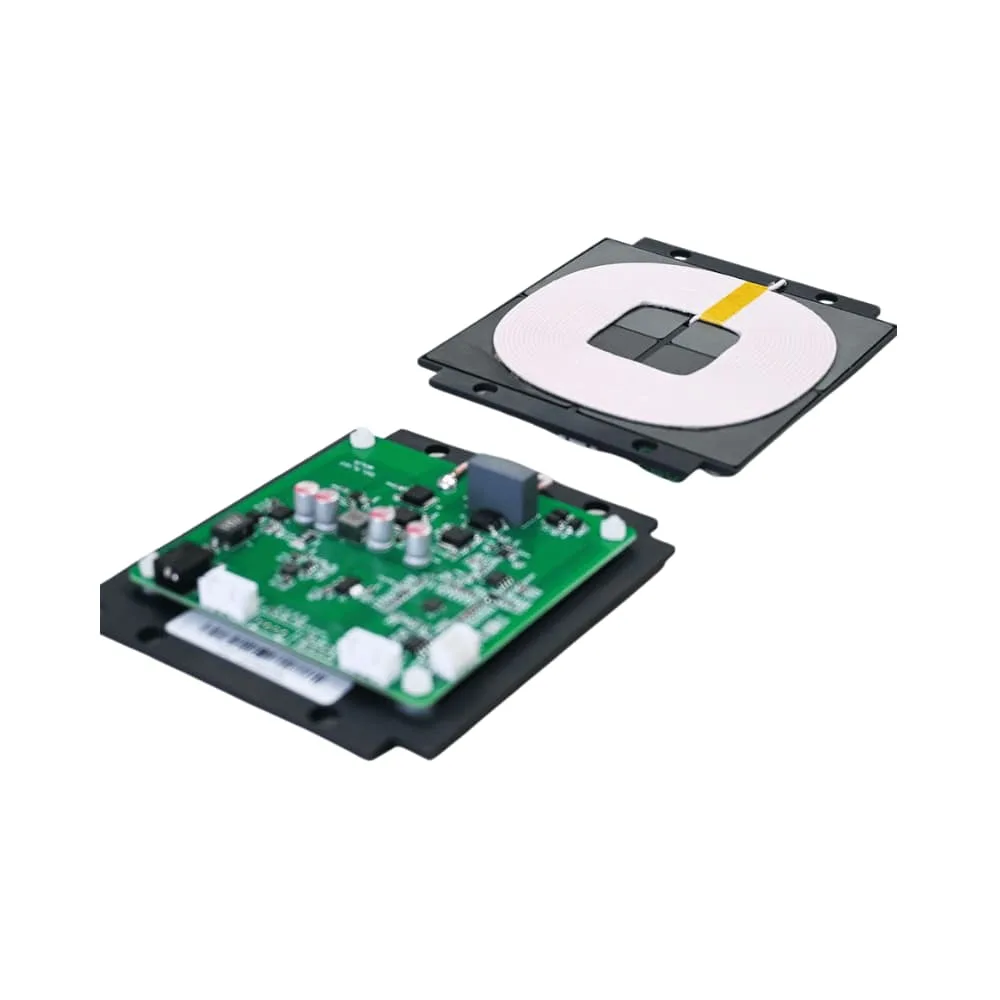
| TD01 parameter | Listed specification | Pool-cleaner design question |
|---|---|---|
| Rated output | 21V DC / 3A, 60W | Does this match the battery's required charging voltage and current? |
| Transmitter input | 24V DC / 4A | Which certified external supply and cable system will feed the dock? |
| Charging distance | 15–35mm, coil to coil | What is the worst-case enclosure and docking tolerance stack? |
| Alignment tolerance | ±10mm horizontal | Can the cradle locate every production robot inside this window? |
| Peak efficiency | 91% at 25mm, DC to DC | What efficiency and temperature are measured in the final enclosure? |
| Coil size | 100 × 100 × 5.5mm | Is there a flat, metal-free integration area on both sides? |
| PCBA size | 90 × 90 × 18mm | Can the sealed compartments provide mounting and thermal clearance? |
| Protection | FOD, OCP, OVP, OTP | What additional system and battery protections are required? |
| Communication | UART / RS485 | Which commands, status signals and failure responses must be integrated? |
TD01 is best evaluated for a compact cleaner whose battery accepts a 21V charging path, whose available dock time suits approximately 60W and whose housing can accommodate the 100mm-square coils. Larger batteries, rapid turnaround targets or incompatible pack voltages require a different design review rather than assumptions based on application alone.
What can be customized for an OEM application?
The standard TD01 remains 21V / 3A, 60W. For a qualified OEM project, ONEPOINTECH can evaluate output voltage and current adjustments within the validated TD01 operating range. The engineering team can also evaluate custom PCB layouts, coil geometry, cables, connectors, firmware and communication interfaces when the customer's mechanical or electrical architecture cannot use the standard module set.
Customization is not an automatic guarantee that every published standard-module specification will remain unchanged. A different coil or PCB layout can affect charging distance, horizontal tolerance, efficiency, electromagnetic behavior and temperature rise. Those parameters must be simulated or measured again in the finished configuration. Development fees, minimum order quantities and additional lead time may apply after the feasibility review.
Prototype and validation plan
- Battery-fit review: confirm chemistry, series-cell count, full-charge voltage, capacity, maximum charge current, BMS limits and target charge time.
- Bench test: validate power-up, regulation, charge termination, communication, foreign-object response and fault recovery with the intended battery architecture.
- Mechanical mock-up: mount both coils behind production-representative wall materials and measure the real coil gap.
- Alignment map: record output, efficiency and temperatures across the complete expected X, Y and angular parking error.
- Thermal test: repeat charging at worst-case ambient temperature, gap and offset inside closed enclosures.
- Wet-condition test: validate the completed housing, drainage and user workflow with water and pool-treatment residue representative of the intended use.
- Foreign-object test: evaluate likely objects and debris around the dock rather than relying only on a clean laboratory condition.
- Cycle and abuse test: repeat docking and charging while checking seals, plastic wear, impact exposure and recovery from interrupted charging.
- Compliance review: define the electrical, EMC, radio-frequency, battery, material and pool-equipment requirements for every target sales market.
The result of this process should be a measured charging envelope: the allowed gap and offset, delivered power, charge time, temperature limits and fault responses for the finished pool-cleaner design.
What to send for a TD01 fit review
To evaluate the 60W module efficiently, send ONEPOINTECH the following information:
- battery datasheet and BMS specification;
- nominal voltage, full-charge voltage, capacity and maximum permitted charge current;
- energy used during a typical cleaning cycle;
- target time from depleted to ready;
- available area for the receiver coil and electronics;
- estimated coil-to-coil distance through both enclosure walls;
- expected docking error and cradle concept;
- operating and storage temperatures;
- waterproofing, cleaning and certification targets;
- whether the project needs standard 21V / 3A TD01 modules or custom output, PCB, coil, cable, firmware or communication development;
- prototype quantity and production forecast.
Use the wireless charging power calculator for an initial energy estimate, then request a TD01 pool-robot charging review. A battery datasheet and a simple section drawing through the proposed coil location will make the first engineering response much more useful.
Product references in this article illustrate market adoption only. Compatibility, waterproofing, safety and regulatory compliance must be validated for the finished product by the equipment manufacturer.